Module mounting system
Flipper One features a module mounting system with two types of modules:
- M.2 module — a standardized internal expansion module that connects to the device’s M.2 B-key port, providing access to high-speed interfaces, SIM/eSIM connectivity, and several GPIO pins. The module can also expose an external antenna connector through dedicated openings in the device’s antenna rail.
- GPIO module — a custom external expansion module that connects to the GPIO port on the back of the device, which provides access to a range of low-speed interfaces including USB 2.0, UART, SPI, ADC inputs, and more.
We have open-sourced the 3D models of the enclosure parts involved in the module mounting system, enabling the community and module manufacturers to design custom enclosure parts.
M.2 modules
The M.2 expansion module (SSDs, cellular or satellite modems, SDR radios, and more) can be installed inside the device via the internal M.2 port. To access the port, the back plate must be removed by unscrewing its mounting screws. The module is then secured to one of the two threaded standoffs on the device’s main board, depending on the module’s length.
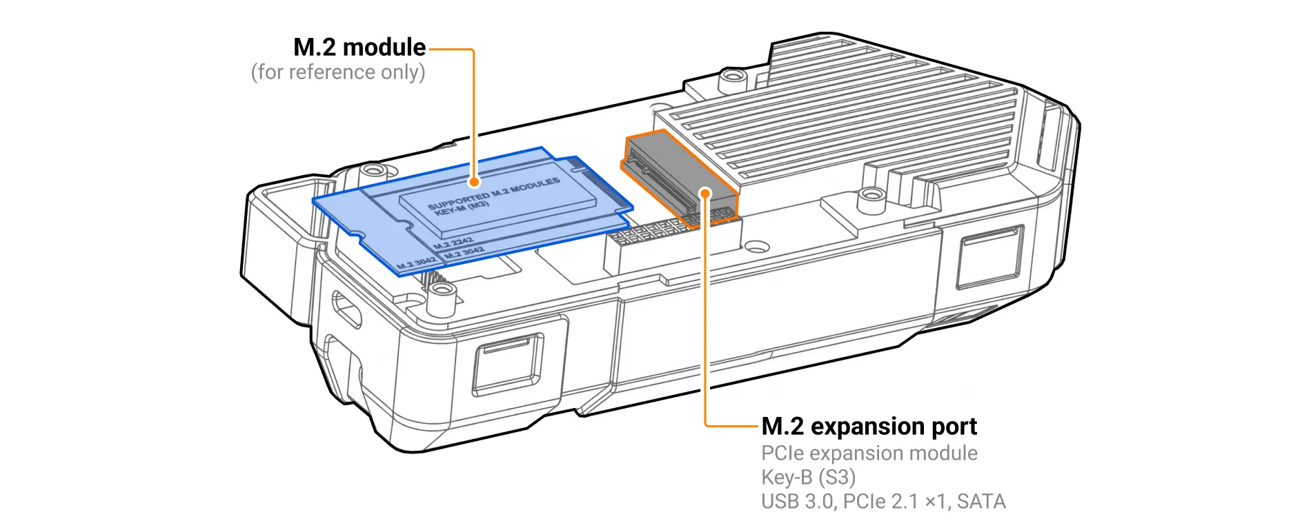
Flipper One supports M.2 modules with top-side component placement (S3 type, with component height up to 1.5 mm above the module PCB). The following module form factors are supported:
- 2230: 22 mm wide, 30 mm long (via extender)
- 2242: 22 mm wide, 42 mm long
- 3042: 30 mm wide, 42 mm long
- 3052: 30 mm wide, 52 mm long
M.2 port pinout and a list of supported interfaces are available on the M.2 portM.2 port page.
Examples of M.2 modules can be found on the M.2 modulesM.2 modules page.
Antenna rail
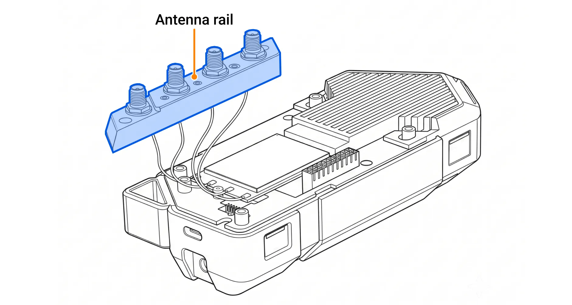
At the top of the rear side of Flipper One, above the back plate, there is an antenna rail — a separate part designed to hold up to four SMA antennas connected to an M.2 module. It is intentionally separated from the back plate, allowing antennas to be installed into the antenna rail and cables to be routed before attaching the rail to the device. This design helps prevent antenna cable damage during assembly.
GPIO modules
The GPIO module connects to the GPIO port on the back of the device.
GPIO port pinout and a list of supported interfaces are available on the GPIO portGPIO port page.
Examples of GPIO modules can be found on the GPIO modulesGPIO modules page.
Module screw mounting
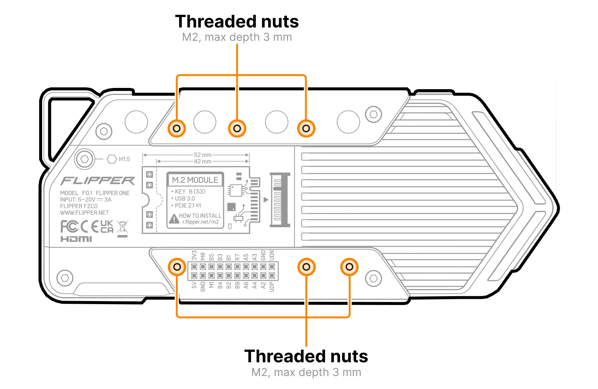
The back plate and antenna rail include six threaded nuts for mounting GPIO modules. The threads are M2, with a maximum screw insertion depth of 3 mm. All threaded nuts are arranged on a 2.54 mm grid, aligned with the GPIO connector pin layout. This makes it possible to build a simple GPIO module from perfboard by cutting it to size and drilling out the existing holes to 2 mm in diameter for mounting to the Flipper One enclosure.
Snap-fit mounting for module cover
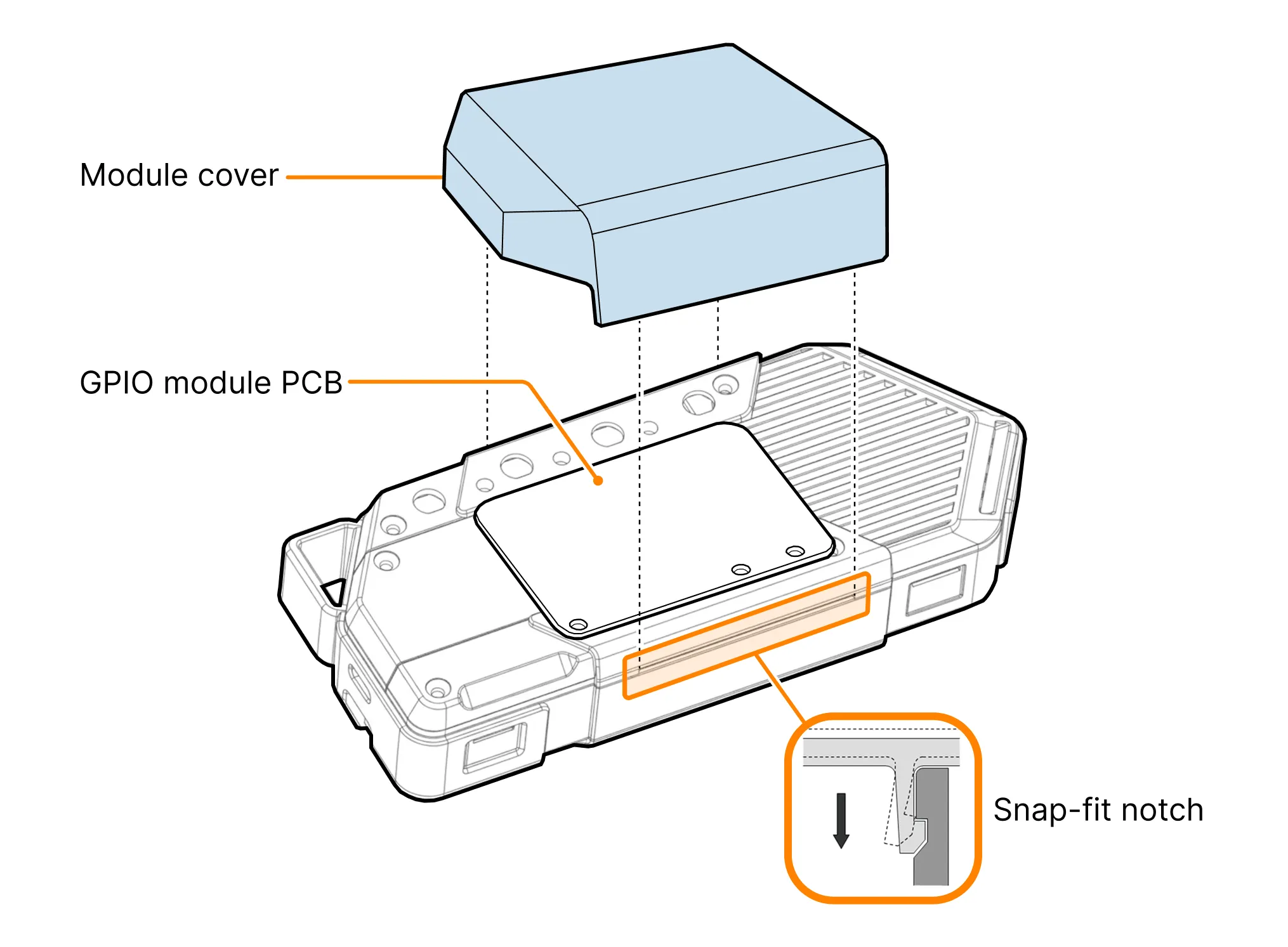
On the Flipper One enclosure, there are two snap-fit notches located on the top and bottom, designed to secure a GPIO module cover to the device body.